Sales & Service>Shaft and housing geometry
Sales & Service
- Main Clients and markets
- Customer Service
- Bearing Selection services
- Bearing Handling Service
- Bearing Fitting Service
- Lubrication Service
- Preload
-
Bearing cleanliness

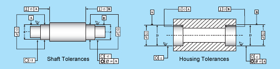
Shaft and housing geometry
In general, machining bearing seats and shoulders in spindles and housings requires careful consideration. The tolerances to which these characteristics should be held are dependant upon the class, size and application of the bearing. In general, these tolerances should be no greater than the total indicator runout (TIR) of the assembled bearing.
● Accuracy of form and position for bearing seatings on shafts and in housings

● ISO tolerance grades for dimensions (lengths, widths, diameters etc.)
|
Nominal dimension |
Tolerance grades | ||||||||||||
| IT1 | IT2 | IT3 | IT4 | IT5 | IT6 | IT7 | IT8 | IT9 | IT10 | IT11 | IT12 | ||
|
over mm |
incl |
max μm |
|||||||||||
| 3 | 6 | 1 | 1.5 | 2.5 | 4 | 5 | 8 | 12 | 18 | 30 | 48 | 75 | 120 |
| 6 | 10 | 1 | 1.5 | 2.5 | 4 | 6 | 9 | 15 | 22 | 36 | 58 | 90 | 150 |
| 10 | 18 | 1.2 | 2 | 3 | 5 | 8 | 11 | 18 | 27 | 43 | 70 | 110 | 180 |
| 18 | 30 | 1.5 | 2.5 | 4 | 6 | 9 | 13 | 21 | 33 | 52 | 84 | 130 | 210 |
| 30 | 50 | 1.5 | 2.5 | 4 | 7 | 11 | 16 | 25 | 39 | 62 | 100 | 160 | 220 |
| 50 | 80 | 2 | 3 | 5 | 8 | 13 | 19 | 30 | 46 | 74 | 120 | 190 | 300 |
| 80 | 120 | 2.5 | 4 | 6 | 10 | 15 | 22 | 35 | 54 | 87 | 140 | 220 | 350 |
| 120 | 180 | 3.5 | 5 | 8 | 12 | 18 | 25 | 40 | 63 | 100 | 160 | 250 | 400 |
● Guideline values for surface roughness of bearing seatings
|
Diameter of seatings |
Recommended Ra value for ground seatings ( Roughness grade numbers ) Diameter tolerance to |
|||
| over | incl | IT1 | IT2 | IT3 |
| mm | μm | |||
| 3 | 80 | 1,6 (N7) | 0,8 (N6) | 0,4 (N5) |
| 80 | 500 | 1,6 (N7) | 1,6 (N7) | 0,8 (N6) |