- Main Clients and markets
- Customer Service
- Bearing Selection services
- Bearing Handling Service
- Bearing Fitting Service
- Lubrication Service
- Preload
-
Bearing cleanliness

A 12-point inspection is suggested to properly inspect a bearing journal or housing bore, verifying the geometry of mating components by comparing the inspection measurements to the suggested mating component tolerance limits.
● Measurement procedure
1. Use two-point gauges that are accurate to 0.002 mm or 0.0001 inches. Gages with accuracy to 1/10 of the units being inspected are suggested, providing resolution to 0.0002 mm or 0.00001 inches.
2. Record the measurements on a chart, being sure to record each measurement for the respective plane and angle. Then calculate the average diameter at each plane.

|
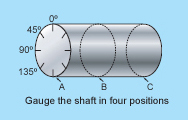
3. Gauge the shaft in four positions, beginning at 0° and then working around the shaft 45°, 90°, and 135° as shown in the left picture. Repeat these measurements at three different planes along the shaft, measuring at the mating surfaces where the shaft will be in direct contact with the bearing. The three planes should be evenly spaced across the contact area. The outboard measurements should be approximately 5 mm (0.2 in.) from the ends of the shaft. |
4. Diameter Evaluation
Compare the average diameter measurement of planes A, B and C to the suggested tolerance limits. Each average diameter should be within the suggested limits. The mating component diameter is out of specification if any average is over or under the suggested limits.
5. Roundness Evaluation
Also compare the individual measurements at each angle of measurement (e.g. compare each of the three measurements taken at 45°?) to the suggested limit. If any measurement is larger or smaller than one half the suggested limit, an out-of-round condition exists.
● Measurements (gages accurate to 0.002 mm/0.0001 in. minimum are recommended)
| 0° | 45° | 90° | 135° | AVERAGES | AVERAGES | |
| PLANE A | A = | |||||
| PLANE B | B = | |||||
| PLANE C | C = |
Roundness is verified by comparing the differences of the four measurements of a given plane. No difference should exceed 0.0006 inches. Straightness is verified by comparing the differences of the three averages. No difference should exceed 0.0006 inches.
● Taper (form) evaluation
Taper is determined by taking the difference between the plane averages as follows:
| AVERAGE A = | AVERAGE B = | AVERAGE C = | ||
| - AVERAGE B = | - AVERAGE C = | - AVERAGE C = | ||
| DIFFERENCE = | DIFFERENCE = | DIFFERENCE = |
Excessive taper exists if any of the differences exceeds the specified tolerance range by more than one half.


