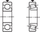
When in service, even a bearing that is properly lubricated, properly installed, and adequately protected from abrasives, moisture, and corrosive reagents, can fail from material fatigue. Material fatigue is manifested as a flaking off of metallic particles from the surface of a raceway or rolling element. This flaking will eventually cause the bearings to fail. The effective life of a bearing is usually defined in terms of the total number of revolutions a bearing can undergo before flaking of either the raceway surface or the rolling element surfaces occurs.
● Machine applications and requisite life
The requisite life of the bearing is usually determined by the type of machine in which the bearing will be used, duration of service and operational reliability requirements. A general guide to these requisite life criteria is shown in the following table.
● Machine applications and requisite life
|
Operating condition |
Application |
Recommended |
|
Short or intermittent operation |
Household electric appliance, electric tools, |
4000 - 8000 |
|
Not extended duration, but |
Household air conditioner motors, |
8000 - 12000 |
|
Intermittent but extended |
Rolling milI roll necks, small motors, cranes |
8000 - 12000 |
|
Motors used in factories, general gears |
12000 - 20000 |
|
|
Machine tools, shaker screens, crushers |
20000 - 30000 |
|
|
Compressors, pumps, gears for essential use |
40000 - 60000 |
|
|
Daily operation more than |
Escalators |
12000 - 20000 |
|
Centrifugal separators, air conditioners, air |
20000 - 30000 |
|
|
Large motors, mine hoists, locomotive axle |
40000 - 60000 |
|
|
Paper manufacturing equipment |
100000 - 200000 |
|
|
24 hr.operation |
Water supply facilities, power stations, mine |
100000 - 200000 |
● Service life of bearing system comprising two or more bearings
Even for systems which comprise two or more bearings,if one bearing is damaged,the entire system malfunctions. Where all bearings used in an application are regarded as one system, the service life of the bearing system can be calculated using the following equation.


|
● Bearing loads When calculating bearing load using the loads on a position on the shaft, it is necessary to calculate center distance between the load application points of the bearings. Deep groove ball bearings have load center points at the center line of the width. Single-row tapered roller bearings, have load center points offcenter to the center line of the bearing width. |
● Magnitude of load
The magnitude of the load is one of the factors that usually determine the size of the bearing. Generally, roller bearings are able to support heavier loads than similar sized ball bearings and bearings having a full complement of rolling elements can accommodate heavier loads than the corresponding caged bearings. Ball bearings are mostly used where loads are light or moderate. For heavy loads and where shaft diameters are large, roller bearings are usually the more appropriate choice.
| Radial load | Axial load | Combined load |

|

|

|
|
Bearings can only support pure radial loads. |
Bearings are suitable for light or moderate loads that are purely axial. |
A combined load comprises a radial and axial load acting simultaneously. |
● Load acting on shafts
It is possible to calculate theoretical values for these loads. However, there are many instances where the actual operational shaft load is much greater than the theoretically calculated load, due to machine vibration and/or shock. This actual shaft load can be found by using formula
| K= fw·Kc |
where, K : Actual shaft load {kgf} fw : Load factor Kc: Theoretically calculated value {kgf} |
● Load factor fw
| Amount of shock | fw | Application |
| Heavy shock | 1.0-1.2 | Electric machines, machine tools, measuring instruments. |
| Light shock | 1.2-1.5 |
Railway vehicles, automobiles, rolling mills, metal working machines, paper making machines, rubber mixing machines, printing machines, aircraft, textile machines, electrical units, office machines. |
| Very little or no shock | 1.5-3.0 | Crushers, agricultural equipment, construction equipment, cranes. |


