Technical>Chamfer measurements and tolerance
Chamfer measurements and tolerance
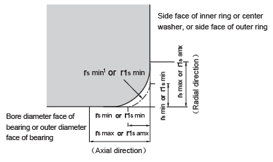
Allowable critical-value of bearing chamfer Deep groove ball bearings
Unit mm
| rs min1 |
Nominal bore diameter |
rs max or r1s max | ||
| or | d |
Radial direction |
Axial direction |
|
| r1s min | over | incl | ||
| 0.1 | - | - | 0.2 | 0.4 |
| 0.15 | - | - | 0.3 | 0.6 |
| 0.2 | - | - | 0.5 | 0.8 |
| 0.3 |
- 40 |
40 - |
0.6 0.8 |
1 1 |
| 0.6 |
- 40 |
40 - |
1 1.3 |
2 2 |
| 1 |
- 50 |
50 - |
1.5 1.9 |
3 3 |
| 1.1 |
- 120 |
120 - |
2 2.5 |
3.5 4 |
| 1.5 |
- 120 |
120 - |
2.3 3 |
4 5 |
| 2 |
- 80 220 |
80 220 - |
3 3.5 3.8 |
4.5 5 6 |
| 2.1 |
- 280 |
280 - |
4 4.5 |
6.5 7 |
| 2.5 |
- 100 280 |
100 280 - |
3.8 4.5 5 |
6 6 7 |
| 3 |
- 280 |
280 - |
5 5.5 |
8 8 |
Notes: These are the allowable minimum dimensions of the chamfer dimension "r" and are described in the dimensional table.
Allowable critical-value of bearing chamfer Deep groove ball bearings
Unit mm
| rs min2 |
Nominal bore diameter of bearing "d" or nominal outside diameter "D" |
rs max or r1s max | ||
| or |
Radial direction |
Axial direction |
||
| r1s min | over | incl | ||
| 0.3 | - | 40 | 0.7 | 1.4 |
| 40 | - | 0.9 | 1.6 | |
| 0.6 | - | 40 | 1.1 | 1.7 |
| 40 | - | 1.3 | 2 | |
| 1 | - | 50 | 1.6 | 2.5 |
| 50 | - | 1.9 | 3 | |
| 1.5 | - | 120 | 2.3 | 3 |
| 120 | 250 | 2.8 | 3.5 | |
| 250 | 3.5 | 4 | ||
| 2 | - | 120 | 2.8 | 4 |
| 120 | 250 | 3.5 | 4.5 | |
| 250 | - | 4 | 5 | |
| 2.5 | - | 120 | 3.5 | 5 |
| 120 | 250 | 4 | 5.5 | |
| 250 | - | 4.5 | 6 | |
| 3 | - | 120 | 4 | 5.5 |
| 120 | 250 | 4.5 | 6.5 | |
| 250 | 400 | 5 | 7 | |
| 400 | - | 5.5 | 7.5 | |
| 4 | - | 120 | 5 | 7 |
| 120 | 250 | 5.5 | 7.5 | |
| 250 | 400 | 6 | 8 | |
| 400 | - | 6.5 | 8.5 | |
Notes: These are the allowable minimum dimensions of the chamfer dimension "r" or "r1" and are described in the dimensional table.