Technical>Load generated under gear transmission

Load generated under gear transmission
|
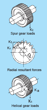
The loads operating on gears can be divided into three main types according to the direction in which the load is applied; i.e. tangential (Kt), radial (Kr), and axial (Ka). Loads acting on planetary shaft gears are depicted in the pictures.The load magnitude can be found by using or formulas: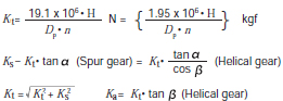 where, Kt:Tangential gear load (tangential force), N Ks:Radial gear load (separating force), N Kr:Right angle shaft load (resultant force of tangential force and separating force), N Ka:Parallel load on shaft, N H:Transmission force , kW n:Rotational speed, r/min Dp:Gear pitch circle diameter, mm α:Gear pressure angle β:Gear helix angle |
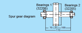 Example: What are the rated lives of the two tapered roller bearings supporting the shaft shown in left chart? Bearing1 is an 32206 with a Cr = 54.5 kN, and bearing 2 is an 32205 with a Cr = 42.0 kN. The spur gear shaft has a pitch circle diameter Dp of 150 mm, and a pressure angle of 20°. The gear transmitted force HP = 150 kW at 2,000 r/min (speed factor n).
● Gear factor fg
Because the actual gear load also contains vibrations and shock loads as well, the theoretical load obtained by the above formula should also be adjusted by the gear factor fg as shown in the table below:
| Gear type | f g |
| Precision ground gears (Pitch and tooth profile errors of less than 0.02mm) | 1.05~1.1 |
| Ordinary machined gears (Pitch and tooth profile errors of less than 0.1mm) | 1.1~1.3 |
● Load on bevel gears
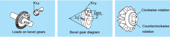
For spiral bevel gears, the direction of the load varies depending on the direction of the helix angle, the direction of rotation, and which side is the driving side or the driven side. The directions for the separating force (Ks) and axial load (Ka) shown in the left picture are positive directions. The direction of rotation and the helix angle direction are defined as viewed from the large end of the gear. The gear rotation direction in the picture is assumed to be clockwise (right).
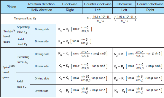
where,
Dpm : Mean pitch circle diameter, mm
Dpm : Mean pitch circle diameter, mm
δ: Pitch cone angle
Herein, to calculate gear loads for straight bevel gears, the helix angle β= 0.